
Therm devices
may be daisy-chained together on a single serial port (up to 16 units).
Each will respond to a unique address.
Each therm can in turn support up to 15 directly-addressed probes,
or an unlimited number in batch mode.
Since the therm uses a standard protocol (RS-232 at 1200 baud)
communication with it is simple and universal:
You can use a terminal to test operation,
run the therm remotely using a modem,
and write your own programs to control it.
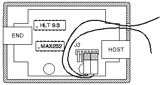
Plug a probe into
the 6-pin header (J3) inside the therm box
(see fig. Section).
You may plug it into either of the positions shown (pins 1-2 or 3-4).
The remaining two pins (5-6) are reserved for other uses.
Which position is not important,
but the polarity is.
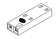
The white dot on the connector must face up, away from
the circuit board.
Probes are connected to the therm via 2-wire cables,
one wire for ground and the other to carry power and data.
All probes connected to a therm are
wired in parallel, even though they have separate plugs.
The DS1820 in each probe has a unique 8-byte id signature built into it,
which the therm uses to find and control it.
With external wiring,
many probes can be connected to a
single therm; see Section.
For information about how probes are addressed from the host
computer, see Section.
As probes are connected and disconnected,
the therm automatically adjusts to the new configuration.
Probe numbers are assigned automatically by finding
all the probe signatures and sorting the list.
This means that adding another probe to a therm can change the numbers of
some or all of the probes already connected (if the signature of the
new probe is lower).
The addressed therm
sends a reply back in one of the following formats:
The temperature reading is always in the same format:
A sign followed by 3.1 decimal digits.
Pound signs indicate that the requested probe doesn't exist (may be
disconnected),
while stars indicate a checksum error while trying to read
the probe,
possibly because the cable is too long or wired incorrectly.
Note:
Make sure the computer serial port connected to Hot Little Therm is set for
No flow control or Raw mode.
Therms do not support hardware (RTS/CTS) or software (XON/XOFF) flow control.
If the serial port is set for flow control,
it may appear that no therm is connected,
or the commands may be eaten by the device driver.
If it's not possible to set the port flow control,
you should still be able to connect to a therm,
but you may need to experiment with looping back flow control
signals (e.g. CTS -> RTS or DTR -> DSR or CD).
If you're still wondering why the probes start at 2 instead of 0,
it's because: this avoids the use of control characters (0x00--0x1F)
for the most common probe addresses.
If you're wondering why the probe number is the top nybble:
there's no particular reason for that.
If a command is sent to read probe number 1 (the "16th" probe),
then all probes connected to the therm are sampled
and a long-format listing is produced instead of a single temperature
value.
The format of the listing is:
Each line of the listing starts with a letter:
One T line will appear for each probe connected.
The first 15 probes listed this way are also directly addressable by using
their individual addresses, as explained above.
The order of the probe ids may not be obvious, but they are always
found least-significant bit of the byte first, left to right.
Note:
In batch mode,
the command to sample the current temperature is broadcast to all probes,
in order to be able to read them more quickly.
This may result in a higher current demand than the 2-wire probe bus
can supply (it works with several probes but not an unlimited
number of them).
See Section about adding a 3rd power wire.
Multiple therms may be daisy-chained on a serial port by
plugging additional units into the END connector.
Outgoing and incoming characters are passed through the therm
between HOST and END ports.
If a command doesn't address the therm directly connected to the serial
port,
it is passed on to the next unit, and so on down the line.
The command byte is not passed transparently through from HOST to END,
instead the unit number part of the command is decremented once at each hop
(the probe number is not changed, for example 0x21 becomes 0x20).
The unit number of every therm is zero --
this allows built-in automatic addressing of therm units.
The first therm attached to a serial port will respond as unit 0,
the second as unit 1, etc.
Note:
This feature affects the programmed unit numbers of older (v.7)
firmware. The effective unit number of a v.7 therm will be higher
by the number of v.9 therms upstream of it toward the host,
because each one will subtract one from the unit number.
The following table shows an example of how a mixture of
version 7 and version 9 therms might be addressed:
If a command doesn't address any therm connected to the serial port,
no response will ever be sent.
Any program that reads the therm device directly must handle this
by setting a timeout when waiting for the response.
A maximum delay of 1 second is sufficient to ensure the therm
has enough time to respond if it is connected.
If you intend to do custom probe wiring,
especially with very long runs of wire or many probes,
we suggest you have a look at the Dallas Semiconductor data sheet
for the DS1820 sensor and
Application Note 108, "MicroLAN in the Long Run",
both
available from at their web site
http://www.dalsemi.com.
Any number of probes can be connected to the therm,
simply by connecting all like ground and data leads together
(see pinout in Section).
They can be daisy-chained on the same cable,
or fanned out in a star, or any combination.
Be sure to read the discussion of long probe wires below.
If you are connecting many probes to a single therm and plan to use
the batch mode command (Section) to read them,
you may need to run a 3rd power wire along with the ground and data
lines.
This is necessary to supply the extra current drawn when all the
probes become active at the same time.
+5V can be drawn directly off the therm board at pin 6 of J3
(see Section).
Also, for this you'll need access to the third pin on the DS1820 (probes are
normally shipped with only the Common and Data pins routed to the
connector.
This would mean cutting apart the rubber covering of the probe.
If you're hooking up lots of probes,
you may want just buy the raw DS1820 chips from Dallas Semiconductor.
You won't have to cut them apart, and they'll be cheaper.
How long can the wire from the therm unit to the probe be?
Quick answer:
A total of up to 300 feet of cable
should work fine, and tests have shown 500 feet to work reliably.
If you use too
much wire, the therm won't be able to read probes correctly.
You'll get "******" or "######" messages
because the CRC checksum will fail.
The main concerns with long probe wires or many probes are:
When sending data to the probes, the therm drives the line both high and
low, and line capacitance is not very important. When receiving, however,
the probes can only pull the line low and must let it float high. To read
a bit from a probe, the therm sends a 4us low pulse and then stops driving
the line. The probe may either drive the line low for 30us nominal to send a
logic-zero, or release it and let it float high to send a logic-one. The therm samples
the line after 15us to determine the bit value. The most critical timing
occurs when the probe sends a logic-one bit. The line must float high through
the pullup resistor within 15us to be read correctly.
The line voltage approximately follows that of a capacitor charging
through a resistor:
Vc = Vs [ 1 - e-t
/ rc ]
In this case, Vs is the applied voltage (5 volts),
Vc is the line voltage, r is the pullup resistor
(5k ohms) and c is the total line capacitance. The capacitance of a single 10' probe (as measured for 10 probes connected
in parallel on the bench) is about 130pF, and this is mostly due to
the cable itself. If we solve the equation with
Vc=2.0 and r=5000 and t=15E-6 we get a
maximum allowable capacitance of around 5800pF. This translates to
around 45 probes, or 450 feet of wire, e.g. any combination of probe wire lengths
up to a total of 450 feet should work.
However, 2.0 volts is marginal, since the capacitance is somewhat
variable, and can depend on where and how the wire is run.
I'd recommend a more conservative limit, say 300 feet.
That is, you could have one probe 300 feet away,
or 10 at a distance of 30 feet each.
Reflections from the far end of the probe cable are the second main concern.
It is not possible to terminate the cable in its characteristic
impedance,
due to the open-collector nature of the bus and constraints
on the minimum value of the pullup resistor.
To obtain the ultimate performance,
an active-pullup circuit is recommended for the driver.
Hot Little Therm uses a simpler circuit,
and limits the slew rate of the negative-going signal (the worst case)
with a series resistor.
This works well enough for moderate (hundreds of feet)
cable lengths.
Here are some suggestions when using long probe cables:
Almost any 4 or 6-conductor phone cable should work as a therm extension cable,
as long as there is a half twist between the two ends (pin 1 on one end
is connected to pin 4 on the other, pin 2 to pin 3, etc.).
Stock phone extension cables will also work,
if you maintain the correct number of half-twists.
There is no hard limit on maximum cable length,
you'll have to experiment.
I've personally run 9600 baud serial cables the better part of a mile.
Caution:
As always when performing electrical wiring, be aware of the environment.
Hot Little Therm does not generate or use any voltages normally considered
dangerous,
but you must be careful when extending the probe or serial port wires
to not let them come in contact with high-voltage (e.g. power or telephone)
lines.
Remember when running wires outdoors that lightning may strike them
and be conducted inside.
One suggested method is to put the probe into a picnic cooler with
an accurate lab thermometer.
Allow some time for the temperature to stabilize (maybe 30 min.),
then quickly read the lab thermometer and note the difference between it
and the Hot Little Therm probe.
If you have several probes,
each one must be calibrated separately (at the same time if you like).
You can now add this offset to the probe reading
(for Unix software, see the thermcap to# entry).
Note:
The probe may have different error offsets at different temperatures,
so you may also want to calibrate it
at two or more points and add a variable correction depending on the
reading (the standard software does not support this).
For a single-point correction,
try to calibrate the probe somewhere in the middle of the
expected temperature range in use.
Hot Little Therm comes with unsupported example software.
It is intended to help you get started using your Hot Little Therm
right away.
We expect you will want to make changes to it
so we include the source code in the distribution.
Explanation of the software in this manual is minimal because we expect
it to change over time.
Each program is documented more fully in README files and manual pages that
accompany the source code.
All the software is fairly portable, and should work on most
any flavor of Unix.
You may need to select compile-time options or tweak it a bit to
get it to work. Check the comments near the top of a program
or in the Makefile to see what can be specified.
Also,
in keeping with the Unix tradition,
the programs are not all-in-one applications,
but rather building blocks that you can use to create other things.
Probem is a utility program that searches a TTY for Hot Little Therms,
reporting any units and probes that it finds.
It can be useful when installing or debugging therm wiring.
Thermplot reads temperature log files and plots a graph of time vs.
temperature, and outputs it as a PPM image.
It can draw on a blank background of any size, or accept a source
image on which to overlay the plot.
Thermplot has lots of options to change the appearance of the graph.
It makes a good building block for web pages.
The therm unit requires a D.C. supply between 8 and 20 volts (9 volts nominal),
and draws about 10mA.
Its operating temperature range is at least 0 - 70 C.
Probes use a C-Grid connector, Molex part number #50-57-9002
This table shows the hexadecimal value and ASCII character equivalent
for probe addresses, by therm unit and probe number.
Addresses 0x80 -- 0xFF are not shown; they are the same characters
repeated, but with the highest bit = 1.
Note:
This equipment has been tested and found to comply with the limits
for a Class B digital device, pursuant to part 15 of the FCC Rules.
These limits are designed to provide reasonable protection against harmful
interference in a residential installation. This equipment generates,
uses and can radiate radio frequency energy and, if not installed and used
in accordance with the instructions, may cause harmful interference to
radio communications. However, there is no guarantee that interference
will not occur in a particular installation. If this equipment does
cause harmful interference to radio or television reception, which can be
determined by turning the equipment off and on, the user is encouraged to
try to correct the interference by one or more of the following measures:
Caution: Changes or modifications not expressly
approved by the party responsible for compliance
could void the user's authorization to operate the equipment.
Spiderplant reserves the right to make changes
without further notice
to Hot Little Therm or to this manual.
Spiderplant makes no claim, express or implied, of the
fitness or adequacy of Hot Little Therm or application software
for any particular purpose or use,
or of the accuracy or completeness of information contained in this manual.
Spiderplant will not assume liability for any loss or damage
caused by the use or misuse of Hot Little Therm
or application software.
Hot Little Therm is not a medical instrument.
Spiderplant
June 6, 1999
Part Number: 101-0001
Table of Contents
Introduction
Hot Little Therm is a digital thermometer designed to be connected
to a computer serial port.
With additional software,
it can be used for temperature logging or control,
to sound an alarm when the temperature exceeds set limits,
and so on.
Parts List
A basic therm set contains the following parts.
Hardware

Connecting Hot Little Therm to the Host
Plug the wall wart into the wall
and the DB-9 or DB-25 connector of the serial adapter into your computer.
Connect the
RJ-11 phone cable between the serial adapter and the HOST port of the
Hot Little Therm box.
That's it.
To connect more than one therm,
see also Section.
Connecting Probes to Hot Little Therm

Probe Addresses
A probe address is composed of a probe number and a therm unit number,
and identifies a single probe in a chain of therms.
The probe number of the first probe connected to a therm
is 2.
As more probes are installed, they are assigned
numbers 3, 4, ..., 15, 0.
This was done to avoid having to use control characters in
the most common cases (a bit weird, I admit).
Probe number 1 activates batch mode (see Section).
Unit numbers start at 0 for the first unit on a serial cable,
and count up.
The following table gives addresses for some probe and unit number
combinations.
Probe Number 1st 2nd 3rd ... 14th 15th Batch Mode Unit
Number1st 0x20 0x30 0x40 ... 0xf0 0x00 0x10 2nd 0x21 0x31 0x41 ... 0xf1 0x01 0x11 3rd 0x22 0x32 0x42 ... 0xf2 0x02 0x12 ... ... 15th 0x2e 0x3e 0x4e ... 0xfe 0x0e 0x1e 16th 0x2f 0x3f 0x4f ... 0xff 0x0f 0x1f Serial Port Protocol
Therms speak RS-232 at 1200 baud, 8 bits with no parity and one stop bit
(1200-8-N-1). The protocol is very
simple, the host sends the therm a command byte:

Output Meaning
[+-]ddd.d<CR><NL> Temperature sample in deg. C
######<CR><NL> Probe does not exist
******<CR><NL> Error reading probe
Batch Mode Protocol
Batch mode allows reading more than 15 probes from a single therm.
There are also other uses for this mode,
for example finding the firmware revision of the therm board
or verifying which probes are connected.
V93-7200 Firmware revision and serial number
S1 Digital input level
T10c0720c00000098 +019.8 Probe (#2) id and temperature
T10ec700c000000d0 -003.5 Probe (#3)
... (other probes)
Z End
Daisy Chaining Hot Little Therms
Connection Order HLT Version Unit Number Set Effective Unit Number 1 (Closest to host) 9 (0) 0 2 7 3 4 3 9 (0) 1 4 (Farthest) 7 4 6 Timing of the Response
Custom Wiring
Connecting Many Probes
Long Probe Wires
Of these, capacitive loading and reflections impose the strictest limits
on cable length.
Long Serial Wires
Auxiliary Digital Input
The therm includes an auxiliary digital input,
pin 5 of J3 (see Section),
that can be read-out in batch mode (Section).
The input is TTL-level, and is protected by a zener diode.
You must supply your own connector in order to use this feature.
Calibrating Probes
The probe chip we use is accurate to +/-0.5 degrees C between
0 and 70C.
If you require greater accuracy, you can calibrate the probe
yourself against a known reference.
Troubleshooting Operation
If you have problems communicating with the therm unit,
try using a terminal or terminal emulator to debug the protocol.
With at least one therm and a probe connected,
sending a space charcter (0x20) will cause the therm to
reply with the temperature of the first probe.
Sending a control-P (0x10) will cause the therm to dump a
reading of its entire state. See Section.
Software
Introduction
Unix
Introduction
therm and thermcap
Therm is the basic program to read data from the Hot Little Therm.
You can install sensors, for example, inside, outside and in the
attic and read them at any time by typing therm inside outside attic.
It uses a
configuration file called thermcap
to
describe all therms and probes connected to a host.
probem
thermplot
xtherm
Xtherm is like thermplot,
but
it displays a temperature graph in an X-window,
rereading the log file every 15 minutes to automatically update the picture.
hltware
Hltware is an all-in-one application that reads and plots
temperatures interactively. It can log to a file, and includes
a simple built-in web server.
Windows
hltware
Hltware (see above) is most complete therm client for Windows.
Macintosh
Therm
Therm is an interactive application that
displays the temperature in real-time on the screen,
and can log to a file.
Electrical and Thermal Specifications
Hot Little Therm uses Dallas Semiconductor DS1820 1-wire thermometer
chips for probe sensors,
with the following temperature specifications:
Operating Temp. Range -55 - 125 C
Resolution 0.1 C
Absolute accuracy, 0 - 70 C +/-0.5 C
Worst case at -55 C +5/-1 C
Worst case at 125 C +1/-3 C
Typical at limits +3/-1 C
Pinouts
RJ-11 HOST (J1) / END (J2) Jacks

Pin no. HOST port END port
1 (optional) Common +9V
2 Common +9V
3 Receive Receive
4 Transmit Transmit
5 +9V Common
6 (optional) +9V Common
Probe Connector (J3)
6 5 4 3 2 1
+5V Digital In Gnd Probe Gnd Probe
DS1820 Probe Chip Pinout

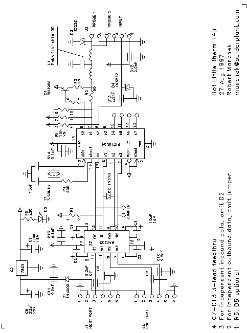
Schematic Diagram

ASCII Table
As no manual would be complete without one...
                 Probe number
                 0 (15th)  1 (batch)  2 (1st)  3 (2nd)  4     5     6     7
               + 0x00      0x10       0x20     0x30     0x40  0x50  0x60  0x70
             0x0   ^@        ^P        spc       0        @     P     `     p
             0x1   ^A        ^Q         !        1        A     Q     a     q
             0x2   ^B        ^R         "        2        B     R     b     r
             0x3   ^C        ^S         #        3        C     S     c     s
             0x4   ^D        ^T         $        4        D     T     d     t
             0x5   ^E        ^U         %        5        E     U     e     u
             0x6   ^F        ^V         &        6        F     V     f     v
Unit Number  0x7   ^G        ^W         '        7        G     W     g     w     ...
             0x8   ^H        ^X         (        8        H     X     h     x
             0x9   ^I        ^Y         )        9        I     Y     i     y
             0xA   ^J        ^Z         *        :        J     Z     j     z
             0xB   ^K        ^[         +        ;        K     [     k     {
             0xC   ^L        ^\         ,        <        L     \     l     |
             0xD   ^M        ^]         -        =        M     ]     m     }
             0xE   ^N        ^^         .        >        N     ^     n     ~
             0xF   ^O        ^_         /        ?        O     _     o    del
RS-232 Connector Pin Assignments
The following table gives the RS-232 standard assignments for
the most commonly used pins,
and shows the ones used by Hot Little Therm.
Abbreviation Signal Name DB-25 Pin DB-9 Pin Therm Use
FG Frame Ground 1 n/a
TX Transmit Data 2 3 Data In
RX Receive Data 3 2 Data Out
RTS Request to Send 4 7
CTS Clear to Send 5 8
DSR Data Set Ready 6 6
GND Signal Ground 7 5 Common
CD Carrier Detect 8 1
DTR Data Terminal Ready 20 4
RI Ring Indicator 22 9
FCC Information
Warranty Information and Disclaimer
Hot Little Therm
may be returned
within 60 days of the date of purchase for a full refund,
if you are unsatisfied with the product for any reason.
Contact
therm@spiderplant.com